Shield Reference
Usage tips
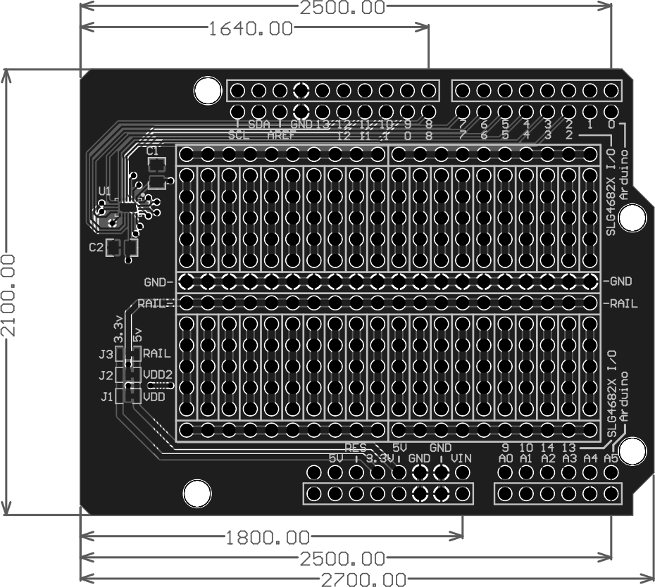
You can cut and solder the VDD and VDD2 pins respectively to connect them to 5V or 3.3V or an external power supply supplying a voltage in between. You can also cut and solder the Rail jumper to switch the center Rail from providing 5V to providing 3.3V.
Pinmap
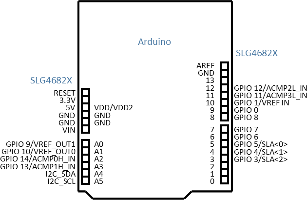
| Arduino IO | SLG4682X Pin |
|---|---|
| A0 | GPIO 9/VREF_OUT1 |
| A1 | GPIO 10/VREF_OUT0 |
| A2 | GPIO 14/ACMP0H_IN |
| A3 | GPIO 13/ACMP1H_IN |
| A4 | I2C_SDA |
| A5 | I2C_SCL |
| 0 | N/A |
| 1 | N/A |
| 2 | GPIO 2/SLA<3> |
| 3 | GPIO 3/SLA<2> |
| 4 | GPIO 4/SLA<1> |
| 5 | GPIO 5/SLA<0> |
| 6 | GPIO 6 |
| 7 | GPIO 7 |
| 8 | GPIO 8 |
| 9 | GPIO 0 |
| 10 | GPIO 1/VREF IN |
| 11 | GPIO 11/ACMP3L_IN |
| 12 | GPIO 12/ACMP2L_IN |
| 13 | N/A |
| AREF | N/A |
| SDA | N/A |
| SCL | N/A |
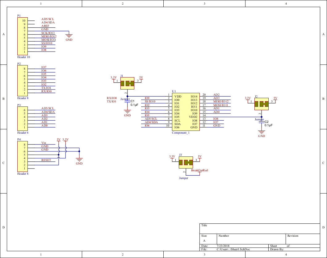
Schamatic
PCB Layout
Source PCB docs (in Altium): SLG4682X-PCB.zip